


Design Tips
In the process of designing my own model landsailers over the last few years I've learned a lot and developed a few calculations that have proven useful. Below you will find a series of mini-articles on model landsailer design as well as a few spreadsheet design tools for making simple calculations. In the interest of promoting this hobby I'm sharing these tools and advice with you.
I'm always trying to improve and add to the information here so if you have any questions about the information below or something that's not here please email me and I'll be happy to discuss it and maybe the answer will end up on this page
LANDYACHT VELOCITY PREDICTION PROGRAM
- Wing Mast Experiments
- Sail Design Tool
- Sail Scaling Formula
- Why Landsailers Don't Have Jibs
- LS Mast System
- Wheel Selection
- Bearing Selection
- Optimum Center of Mass (ballast location)
- Expected Loads
- Beam Bending Analysis Tool
- Speedometer Setup
- Generating down force with rear beam
- Center of Lateral Resistance
- Optimizing Length/Width Ratio for Maximum Righting Moment
General Design Issues
This article is an attempt to describe the big picture of model design. In general there are two primary measurements of model performance; acceleration and top speed and the following description explains which model variables affect these two performance characteristics.
Acceleration
Acceleration is important when racing around a course when you need to change directions and get the most speed out of each gust. The very simple relationship that determines acceleration is Force = mass x acceleration. It says that a body experiencing a force will have an acceleration that is equal to the net applied force divided by the body's mass. This means that one way to increase model acceleration is to make it as light as possible. Alternatively, you can increase the net force by increasing the thrust generated by the sail or by decreasing the model drag. Increasing the sail thrust can be done by improving the sail lift to drag ratio (like using a wing mast) or by increasing the sail area. Since you need more weight to carry more sail area you can see that there must be some balance between model weight and sail area. The other way to increase net force is to reduce model drag. In practice this in not very effective because drag force is proportional to velocity squared. When accelerating from low speed these forces are small compared to the sail thrust and so body drag is not very important to acceleration. In fact, if the model is moving downwind and has not yet reached wind speed a larger body drag force may actually increase acceleration.
The conclusion is that model mass, sail lift/drag ratio and sail area are the primary variables that influence model acceleration. Acceleration can be improved only by increasing the sail lift/drag ratio and correctly balancing model weight with sail area.
Top Speed
Top speed is important when racing in a straight line on a long leg of a course. Calculating maximum model velocity is more complicated than acceleration but we can still determine the primary factors that influence it. Maximum model velocity occurs when the thrust force generated by the sail is equal to the combined drag force of the sail, body and wheels. Model weight has no direct correlation to maximum velocity. Instead we must consider the lift/drag ratio of the sail, the sail area, the aerodynamic drag of the model body and the drag in the wheels. Maximum velocity can be increased by improving the sail lift/drag ratio, increasing the sail area and decreasing the model drag. Because sail area must still be balanced with model mass, one way to increase top speed is to carry a large sail and make the model very heavy but this will adversely affect acceleration and maneuverability.
The best way to increase top speed, besides improving the sail performance, is to reduce drag by using low friction ball bearings in the wheels and making the body slim and streamlined to reduce friction.
Conclusions
Increasing the lift/drag ratio of the sail increases model acceleration and top speed while sail area and model mass must be properly balanced for optimum performance. In addition, reducing the model drag from the body and wheels will increase model top speed but has little effect on acceleration.
LANDYACHT VELOCITY PREDICTION PROGRAM
Program Description
The program described here is a Matlab script that was written to predict the speed and loading on a landyacht based on the yacht configuration, the wind conditions and the vehicle heading. To run the file you need a version of Matlab or you will need to convert the algorithm to some other language but you can at least view the file with WordPad. The algorithm doesn't make any assumptions about the size of the landyacht and so it is valid for models and full size landyachts alike. I don't have much data to compare the results to but it seems to at least be in the right ballpark for predicting yacht speeds.
The program works by guessing at and then adjusting the vehicle velocity until the net thrust is close to zero (steady state operation, i.e. top speed) for all possible headings (0-180 degrees) and sail/wing trim angles (0-60 degrees). It then stores the maximum velocity for each heading that also satisfies the criteria that the vehicle can't flip over or slide sideways. It also stores the maximum possible velocity when slipping and flipping are ignored so that you can see how close your design is to achieving it's maximum possible speed. This information is then plotted in a polar plot like the one below:

The red line represents the maximum speed when flipping and slipping are ignored. The blue line is the maximum vehicle velocity when flipping and slipping are taken into consideration. In this case, the yacht could achieve greater speeds if it were made heavier or if it made use of down force. One useful aspect of this program is that it can be used to predict how much weight is required to prevent slipping and flipping for given wind conditions and yacht configurations. Based on this information the program can also estimate the loads the vehicle will experience for any wind speed, yacht speed, rig trim and heading.
To use the program to simulate your own yacht you just need to change the yacht parameters to match your own design and run the script for the wind speed you're interested in. If you do use this program in the design of a full sized landyacht or a model, please send feedback to info@rclandsailing.com along with any real data you have to compare to predictions. If you do not have access to Matlab, I will be happy to run the script for you if you provide me with the necessary yacht parameters.
To download the script right click the link below and "save as"
Matlab Velocity Prediction Script
Richard Loftin of Wind Wheels Online Landsailing Journal has translated this script into a Java program that anyone can run. To see it in action click here.
John Horstkamp, a student at George Mason University, has translated this script to a program that can be run on any Windows machine. To download the zipped file, click here.
Wing Mast Experiments
I have constructed several wing masts for the LS-3 and LS-4 platforms. The wing is similar in construction to a model plane wing with slight modifications to the trailing edge allowing for a sail slot. The balsa and basswood wing skeleton is shown below.
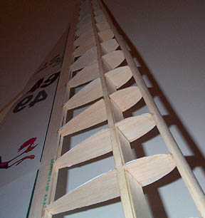
The wooden skeleton is then covered with monokote heat shrink aircraft covering to form the surface. This construction is very light, extremely strong and relatively inexpensive.
In light wind conditions (less than 15 mph) a small sail is attached using the LS-3 quick change groove system. In heavier wind conditions the sail is removed and the wing alone can be used to power the model. Though this configuration is faster than the storm sail rig it is much more sensitive and therefore more difficult to sail.
The resulting rig noticeably outperforms the standard rig reaching speeds 30-40% greater than the rectangular mast with mylar sail. To see the detailed data see the speedometer section.
The most interesting observation I have made so far is that wing thickness and tapering have no noticeable effect on wing performance. The only important variable seems to be wing area which must be balanced with the model righting moment. With this in mind, the LS-3 wing mast has been designed to provide sufficient power by itself in a 20 mph breeze. In lighter conditions the addition of the mylar sail increases the rig power so that the wing rig can outperform the stock mast and sail in all wind conditions. The LS-3 in now available with a wing mast option for a small increase in cost, and the wing mast is standard on the LS-4.
Sail design tool
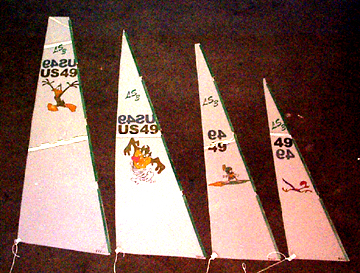
This spreadsheet is meant to make sail design a little faster. It takes a few inputs, such as luff length and rake angle, and calculates sail area, the location of the center of effort and draws a simple picture of what the sail will look like. I use it to quickly run through a few different sail plans before I start cutting. Because the materials are relatively cheap, it's a good idea to build a few sails for different wind conditions like windsurfers do.
Sail Scaling Formula
This article develops an equation for determining an appropriate scaling factor for making a sail bigger or smaller than an existing sail that is already known to work well in a particular range of wind conditions. This is intended for making multiple sails for use on the same yacht. It may not be valid for estimating appropriate sail scaling between different yachts. The equations presented assume a triangular sail shape that is scaled in such a way that the aspect ratio is maintained from one sail to the next, though this same approach could be used to derive the scaling laws for differently shaped sails as well.
Lets say you already have a sail that works great on your model in 10 mph winds and you want to make a similarly shaped smaller sail for 20 mph winds (Of course, wind is variable so when we talk about 10 or 20 mph winds, what is meant is wind conditions with an average speed near that level). To accomplish this objective, you will need to reduce the size of the sail enough that the new sail generates the same amount of heeling moment in 20 mph winds that the old one did in 10 mph winds. But how much smaller should you make it? Changing the size of the sail makes the yacht better suited for more or less wind for two reasons. First, the sail size affects the sail area, which governs the magnitude of the forces generated by the sail. Second, the sail size also affects the location of the sails center of effort, which governs the effect that the sail force will have on the yacht. Because the center of effort changes, the mast step will also have to be shifted either forward or backwards to maintain proper helm balance. Another result of this effect is that since a smaller sail will have a lower center of effort, it can generate higher forces before exceeding the yachts maximum stable heeling moment. This means that more thrust can be generated before the yacht will tip, which is one of the reasons that yacht speed increases as wind speed increases.
Scaling Equation
Variables:
S - sail scaling factor you want to compute (scaling of each sail dimension)
R - ratio of new design wind speed to old design wind speed (in this example R = 20mph/10mph = 2)
The following is a scaling equation for a triangular sail shape (click here for derivation):
S = R^(-2/3)
When plotted this function looks like this:

There is also an excel worksheet that will perform this calculation for you: click here.
Example
An example of how to use this formula will now be presented. Although in this example, the formula is used to scale down, it can also be used to scale up. Assume you already have a sail that works well in 10 mph winds with the following dimensions:
Original sail dimensions:
Foot (triangle base b) = 10 in
Leach (triangle height h) = 50 in
Area A = 250 sq. in
Now you decide that you would like to make a new sail that will generate a similar heeling moment in 20 mph winds. The variable R is 20 mph/10 mph so R = 2. Using the above equations or plots, when R = 2, S = 0.63. Now we multiply the original sail dimensions by S to get the new dimensions:
New scaled sail dimensions:
Foot (triangle base b) = 10 in x 0.63 = 6.3 in
Leach (triangle height h) = 50 in x 0.63 = 31.5 in
Area A = 99 sq. in
While this method does not take into account differences in mast bend, Reynolds number and other secondary effects, it should provide a very good estimate for scaling up or down from an existing sail configuration. Once the mast step is repositioned properly, this new sail should behave similarly in 20 mph as the original did in 10 mph winds.
Why Landsailers Don't Have Jibs
It seems that every soft water sailor who contacts me asks why my models don't have jibs.
To understand the difference between soft water sailing and landsailing you must think about working in an entirely new realm of speed where the effect of apparent wind actually exceeds the true wind. Because the resistance to forward motion is so small on a landsailer, it will quickly reach wind speed at almost any point of sail other than head to wind. At that point the vehicle speed will increase further based on the combined effect of the true wind added to the apparent wind. This makes it possible to reach speeds in excess of 3 times wind speed! This means that once under way, a landsailer (even a model) is essentially going upwind no matter what it's angle to the true wind.
At these high speeds and low angles of attack a single sail rig is vastly superior to a multi sail rig because it can generate a higher lift to drag ratio than multiple sails. This is why you will never see a modern land yacht with a jib (see http//www.nalsa.org/) or a bi-plane for that matter. The same reasoning applies for models. When you're sailing a monohull these effects are not apparent because of the limits of hull speed, but you don't need to be going 60 mph to see this effect. If you've ever sailed on a modern beach catamaran you know that in an upwind leg a jib is often a hindrance which is why the fastest cats use a single, wing like main sail for upwind work and a retractable reaching sail for downwind work.
I hope this explanation satisfies anyone's urges to try a jib on their land yacht. While I enjoy and encourage experimenting with new rigs and configurations to enhance model performance this is one test that has been done many times before. Why not try a wing instead!
LS Mast System
Since I've heard quite a few questions about my spring loaded side stays I've provided a short description below.
The spring loaded side stays themselves are a relatively simple system of lines and fatigue resistant rubber bands that
allow the sail to lean to leeward. By adjusting the pre-tension in the system, the amount of
 lean can be adjusted.
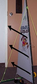
One benefit of this system is that in sudden gusts, the sail leans to leeward and naturally spills wind to prevent capsizing.
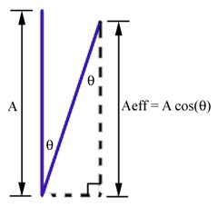
You can think of this as reducing the effective sail area. This is illustrated in the accompanying figure.
As the mast leans over an angle theta, the effective sail area becomes the actual sail area multiplied by the cosine
of the angle.
lean can be adjusted.
One benefit of this system is that in sudden gusts, the sail leans to leeward and naturally spills wind to prevent capsizing.
You can think of this as reducing the effective sail area. This is illustrated in the accompanying figure.
As the mast leans over an angle theta, the effective sail area becomes the actual sail area multiplied by the cosine
of the angle.
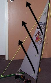
As it turns out, I've found that model performance is also very dependent on rig tension. Specifically, the model is much faster when the sail leans to leeward. This behavior is much harder to explain, but I'll try.
These figures try to show the difference in the vectors of the air flow over the sail for a vertical and tilted configuration.
|
|
With the sail vertical, the air is forced to flow approximately parallel to the foot of the sail so that the resultant forces on the model are to leeward (which causes sliding) and forward (to cause forward acceleration).
When the sail is leaning to leeward, the air flows upwards and to leeward (parallel to the mast). That results in two forces down and to windward that weren't present when the mast was vertical. This additional force to windward (which counteracts the leeward force and improves balance) may explain the better performance of the tilted rig.
Wheel selection (urethane inline skate wheels vs. foam RC plane wheels)
I have also tried both types of wheels and there are three main reasons I feel urethane wheels are better than foam plane wheels for model landsailers.
- Urethane wheels are equipped with ball bearings and foam plane wheels aren't resulting in reduced friction for inline skate wheels.
- Traction- friction force is a function of both weight and coefficient of friction. Both of these have larger values for urethane wheels (especially soft ones) than for foam plane wheels and that reduces side sliding.
- Stop thinking like a soft water sailor! As a catamaran sailor I know what a great speed advantage it is to reduce boat weight, but that is because the amount of water displaced by the hulls, and thus drag, is proportional to boat weight. For a landsailer with ball bearings, drag is not a strong function of weight and so if you can add some weight at the very end of the beam then you increase the righting moment and can carry a larger sail. There is still the drawback of slightly reduced vehicle acceleration but in my experience, that doesn't have much affect on a landsailer that already possess great acceleration.
And now thanks to the increased popularity of foot scooters urethane wheels with diameters of 125 mm and even larger are now available.
If you are planning on purchasing inline skate wheels I recommend the closeout deals at www.skatepro.com
Bearing selection
There are many grades of bearings available for roller blade wheels and I have tried several to determine the impact of bearing quality on model speed. Delrin bearings range in quality from ABEC 1 to ABEC 3, 5 and 7 with ABEC 1 being the slowest and cheapest (about $1 each) and 7 the fastest and most expensive (about $2.50 each). There are also ceramic bearings available that are even faster and more expensive ($5 or more each).
When used on inline skates or skate boards you can notice great differences in bearing performance because each set of bearings is supporting 20-40 pounds. On a model landsailer each set of bearings supports about 1-2 pounds. This small load makes the advantages of "better" bearings much smaller.
To test the effects of bearing quality on model speed two identical LS-3's were raced. One was fitted with ABEC 1's and the other with ABEC 7's. The result was that the LS-3 equipped with ABEC 7's had a slight advantage in wind conditions from 5-8 mph though it was barely noticeable. In winds in excess of about 8 mph no difference could be noticed.
These results lead to the conclusion that high quality bearings may be slightly advantageous for racing but do not have as much effect on speed as other features such as beam, mast and sail configuration.
Optimum Center of Mass
This section describes the best way to position weight on your model in order to counteract the force of the wind on the sail. This approach does not take into account the effect of weight distribution on model balance and vibration which should also be considered.
On a landsailer, as with any wind powered vehicle, it is beneficial to minimize overall weight to increase acceleration. Of course, some weight is required to counteract the force of the wind that tries to flip the vehicle over. How this weight is distributed determines how much righting moment (the thing that keeps you from flipping) you have per unit mass. The goal is to maximize the righting moment per unit mass so that you get the most benefit from the weight you carry. In the LS designs overall weight is minimized first and then the majority of the model weight is concentrated in the area that yields the most righting moment.
There are two methods for determining the optimum weight distribution and both lead to the same conclusion. Both methods are described below.
The results show that the best place to put the majority of the model weight is a far to the stern as possible. Furthermore, whether you concentrate the model weight at the ends of the rear beam or at the center, there should be little difference as long as the weight is balanced side to side and is far rear as possible.
Energy-Work approach
One way to approach this problem is to say that the rig must do some work on the mass of the vehicle to lift the windward wheel. If the goal is to prevent this from happening, then lifting the windward wheel a given amount should require as much work as possible. Work (or energy) is equal to force times distance. In this case, the force is the weight of the vehicle and the distance is the height that weight is raised off the ground.
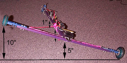
To maximize the energy required to lift the wheel for a given model weight all the weight should be put where it will move the most as the wheel comes off the ground. Based on the geometry of a 3 wheeled landsailer, this distance is largest at the rear of the model near the windward wheel. Since the weight must also be symmetrically distributed for vehicle balance we can consider two cases:
If all the weight (let's say 2 pounds) is at the center of the rear beam then the work done is 5" x 2 pounds = 10 inch-pounds total.
If there are two equal weights (1 pound each) located at each end of the rear beam then the total work done is 10" x 1 pound = 10 inch-pounds total. The other pound of weight doesn't contribute because it doesn't move as the vehicle tilts. The result will be the same if the 1 pound weights are located any distance from the center as long as they are symmetric.
So as long as the weight is far rear it doesn't make any difference how you distribute it along the rear beam as long as it's symmetric.
Moment approach
We can also model the sail as exerting a moment on the model that must be counteracted to keep the model from flipping (or forcing you to let out the sail). In this case we want to maximize the moment exerted by the model weight. Since moment is distance times force you want your weight in a place where it is far from the point of rotation (the leeward rear wheel).
For example, say your beam is 30" long. If you put 1 pound of ballast at each end of the beam then as the windward wheel lifts off the ground the weight at the leeward end does nothing to counteract the sail force because it's not moving. The weight at the windward end it being lifted and is 30" from the rotation point so it exerts a moment of 30 inch-pounds (1 pound x 30") keeping you from flipping.
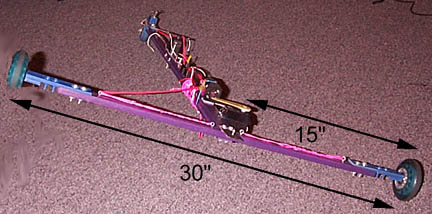
Now consider if instead of 1 pound at each end, you put 2 pounds in the center of the beam. As the windward wheel lifts off the ground all 2 pounds will move but now the moment arm is only 15" long and so the total moment is still 30 inch-pounds (2 pounds x 15").
So once again, as long as the weight is far rear it doesn't make any difference how you distribute it along the rear beam as long as it's symmetric.
Expected loads
By analyzing the failure mode of an early model, I was able to estimate the maximum load you can expect the main beam will have to support which can then be used to get an idea of how strong you need to make it.
In this case, a composite balsa/basswood I-beam fractured from the force of the sail pushing down on it.
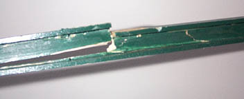
The wind was blowing approximately 20 mph when this beam failed just forward of the mast step. Based on the material properties and the loading geometry, I found that the force exerted on the beam by the sail must have been at least 25 lbs. The area of the sail being used was 250 in2. So assuming this force increases linearly with sail area (which is probably a good approximation) this should give you a rough idea of how much load your model must support for a given sail area in 20 mph of wind.
Bottom line: To get a rough idea of how much load your beam will see in a 20 mph breeze, take your sail area in square inches and divide it by 10 to find the expected load in pounds.
Beam bending
This spreadsheet is an aid in designing beams for the main spar, rear beam and mast cross sections. It helps calculate the bending of a simple wooden beam for a given loading situation and could be modified to work for more complex structures and different materials.
Speedometer Experiments
I've been working on a system to more accurately measure model speed. To refine the measurement, I've purchased a bicycle cyclometer and fastened it to one of the rear wheels as seen in the accompanying pictures.
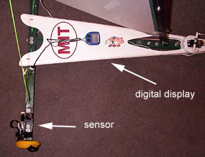
This cyclometer is an avocet cyclometer model 15 which was chosen for its capability to be programmed for wheel circumferences as small as 100 mm eliminating the need to convert the display's velocity read out. This model also has a maximum speed function which is required on a model if you wish to see how fast you were going.
The system is relatively cheap and simple to put together but the initial results were disappointing. The speedometer hit a limit at 11.2 mph, and was incapable of measuring any higher speeds on the 80mm wheels. Since the recommended sensor position is 3" from the axle with a top speed measurement of 75 mph, and on the model it was mounted approximately 1" from the axle, the maximum speed expected is about 25 mph. This suggested that there was a mounting/alignment problem that needed to be corrected before an accurate velocity measurement could be made.
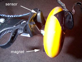
The magnet was remounted on a larger 110mm urethane wheel and the maximum speed increased to 15 mph but did not work at higher speeds as you can see in the following plot.
Preliminary results are shown here for the LS-3 with the standard sail (pink) and with the developmental wing mast (blue) though no data has been taken yet in winds over about 9 mph. The horizontal axis represents wind speed and the vertical axis is model speed. As you can see the LS-3 exceeds wind speed by 50-100% and may even do better in higher winds. The velocity curves fall off at higher speeds because the speedometer is currently not capable of measuring speeds greater than 15 mph.
Generating down force with rear beam
Traditionally in any sailing vehicle the only force that is used to counteract the sail and keep the vehicle from flipping over is weight. An alternative is to generate an aerodynamic force (down force) to counteract the sail. In most sailing vehicles the air velocity simply isn't large enough to easily generate significant amounts of force but on a model landsailer apparent wind velocities can easily reach twice wind speed. This makes it possible to use the model's rear beam to generate an appreciable down force (about 1/4 to 1/3 of the model weight). This can be accomplished by making the rear beam in the shape of an asymmetric airfoil. The drawback is that an asymmetric airfoil creates more drag than an equally sized symmetric foil.
To determine if the benefits of this design outweigh the extra drag the performance of the LS-4 prototype design was simulated for a symmetric rear beam and a down force generating asymmetric beam. The polar plot of vehicle velocity vs. wind angle is shown below for both designs in a 20 mph breeze. The result is that the asymmetric design, shown in blue, is slightly faster (about 1 mph) than the symmetric design for most points of sail. Both designs are predicted to reach speeds of 28 mph using the wing mast alone in the 20 mph breeze.
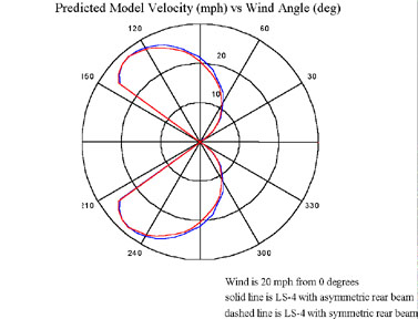
During some initial tests on the prototype LS-4 this technique seems to have some large benefits. The result is a much more stable model with no noticeable affect on top speed. This is possible because the slight increased in air drag is balanced out by the fact that the model can safely carry more sail area and use more of the existing power to generate more thrust without flipping.
Locating the Center of Lateral Resistance
Lateral resistance is the force or forces that oppose sideways motion in a yacht (land or otherwise). It is important to know where the center of lateral resistance is so that you can position the sail's center of effort nearby to control the helm (the tendency of the yacht to turn up into the wind or down away from the wind when you stop steering). In the case of a boat, the lateral resistance is provided by the hull and the foils (i.e. rudder and center board). On a landyacht, the friction between the wheels and the ground provides the lateral resistance. The center of lateral resistance (CLR) is the point along the length of yacht where, if you push it sideways, it will slide sideways without rotating. You can also think of this point as the place where all the lateral resistance force would be acting if it was only a single force, rather than forces on several different wheels. To find out where the CLR is on your yacht, set it up on the ground and push it sideways with your finger. Search for the place where the boat doesn't rotate as you push it. It turns out that on a landyacht, under static (i.e. non accelerating) conditions, the center of lateral resistance will be the same as the center of gravity (CG), provided that the coefficient of friction for the front and rear wheels is the same. The figure below shows the static force and moment equations for a landyacht.

These equations show that the CLR and the CG are the same as long as the friction is the same for all the wheel. If the friction at one wheel is greater than at another, then the CLR will be shifted towards the wheel with the higher friction. Once you start sailing, the forces on the sail will have an effect on the weight carried by each wheel, which will also shift the CLR slightly. That is why the static determination of the CLR may only be good enough for a first guess at where to place your sail for proper helm. After that, you will probably need to experiment a little to find the position that gives you the helm you want.
Optimizing Length/Width Ratio for Maximum Righting Moment
The length-to-width ratio (L/W) of a three-wheeled landyacht affects the righting moment available to keep the yacht from flipping. This is because the moment arm (the distance from the center of gravity (CG) to the line about which the heeling yacht rotates) changes as the L/W ratio changes. The figure below demonstrates this.
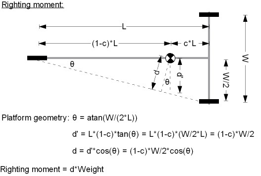
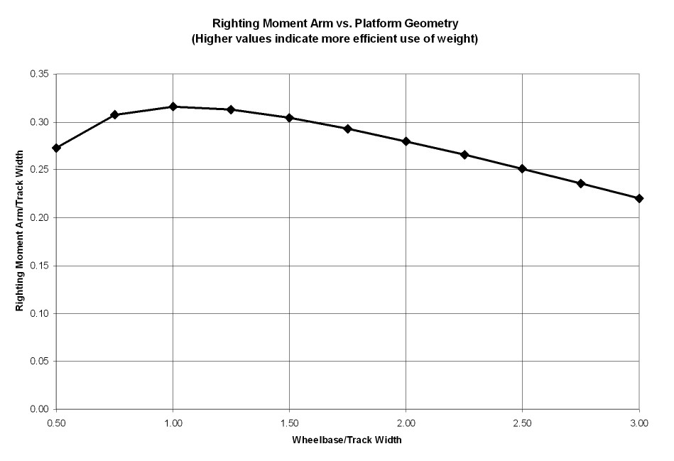
The distance "d" in this figure is the moment arm and as you can see, as the yacht gets very long (L/W -> infinity) d approaches half the rear axle width (w/2). As the yacht becomes very short (L/W -> 0), d approaches zero. This relationship is demonstrated in the following dimensionless plot.

The plot shows that for small L/W ratios, the righting moment arm increases quickly and then levels off. Based on this analysis, you might think that the longer you make your yacht, the better, although most of the benefit is had once you get to L/W = 1.5. It also shows that as the CG moves backwards, the righting moment increases. However, the previous plot assumes that the CG can be moved independently of yacht length, but in reality the CG will move forward as the length increases. Exactly how much the CG will move depends on the specific design of the yacht. To quantify this relationship, the LS-3 design was chosen to determine the approximately relationship between length and CG position. This next figure shows the normalized moment arm (d/w) when we account for the relationship between length and CG position (based on the LS-3 design).
This shows a more realistic picture of what is happening as the L/W ratio changes. Now you can see that the maximum righting moment arm is reached at an L/W ratio of about 0.8 to 1.3. However, L/W ratios at or less than 1 have undesirable behavior because the fore-aft stability becomes an issue when the windward wheel begins to lift off the ground. A good compromise is an L/W ratio around 1.3-1.5, which is a value commonly seen in full scale landyachts and models alike. In fact, the IRCSSA class rules, when maxed out, result in L/W ratios of 1.3-1.5.
More to come soon... And if there is an aspect of model design you would like to discuss, please send your suggestions, questions or comments to info@rclandsailing.com